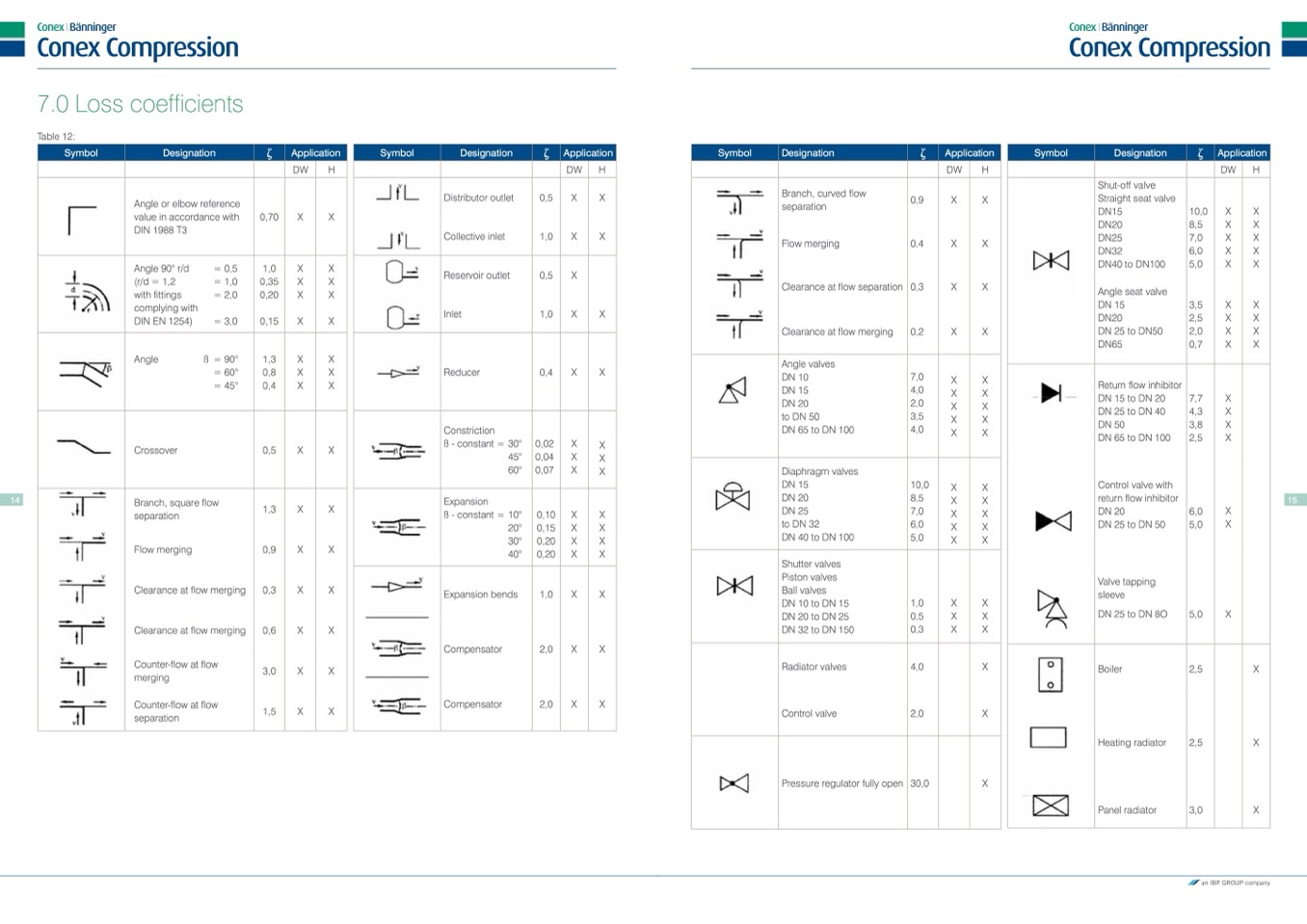
7.0 Loss coefficients
Table 12:
Symbol
Designation
Application
Symbol
Designation
Application
Symbol
Designation
Application
Symbol
Designation
Application
D
W
H
D
W
H
D
W
H
DW
H
Angle or elbow reference
value in accordance with
DIN 1988 T3
Angle 90° r/d
(r/d = 1,2
with fittings
complying with
DIN EN 1254)
= 0,5
= 1,0
= 2,0
= 3,0
Angle
ß = 90°
= 60°
= 45°
Crossover
Branch, square flow
separation
Flow merging
Clearance at flow merging
Clearance at flow merging
Counter-flow at flow
merging
Counter-flow at flow
separation
Distributor outlet
Collective inlet
Reservoir outlet
Inlet
Reducer
Constriction
ß - constant = 30°
45°
60°
Expansion
ß - constant = 10°
20°
30°
40°
Expansion bends
Compensator
Compensator
Branch, curved flow
separation
Flow merging
Clearance at flow separation
Clearance at flow merging
Angle valves
DN 10
DN 15
DN 20
to DN 50
DN 65 to DN 100
Diaphragm valves
DN 15
DN 20
DN 25
to DN 32
DN 40 to DN 100
Shutter valves
Piston valves
Ball valves
DN 10 to DN 15
DN 20 to DN 25
DN 32 to DN 150
Radiator valves
Control valve
Pressure regulator fully open
Shut-off valve
Straight seat valve
DN15
DN20
DN25
DN32
DN40 to DN100
seat valve
Angle
DN 15
DN20
DN 25 to DN50
DN65
0,70
X
X
1,0
X
X
0,35
X
X
0,20
X
X
0,15
X
X
1,3
X
X
0,8
X
X
0,4
X
X
0,5
X
X
1,3
X
X
0,9
X
X
0,3
X
X
0,6
X
X
3,0
X
X
1,5
X
X
1,0
X
X
0,4
X
X
0,5
X
10,0
X
8,5
X
7,0
X
6,0
X
5,0
X
3,5
X
2,5
X
2,0
X
0,7
X
7,7
X
4,3
X
3,8
X
2,5
X
6,0
X
5,0
X
5,0
X
2,5
2,5
3,0
X
X
X
X
X
X
X
X
X
0,5
X
X
0,9
X
X
1,0
X
X
0,3
X
X
0,2
X
X
0,4
X
X
7,0
X
X
4,0
X
X
2,0
X
X
3,5
X
X
4,0
X
X
Return
DN 15
DN 25
DN 50
DN 65
flow inhibitor
to DN 20
to DN 40
to DN 100
0,02
X
X
0,04
X
X
0,07
X
X
14
10,0
X
X
8,5
X
X
Control valve with
return flow inhibitor
DN 20
DN 25 to DN 50
Valve tapping
sleeve
DN 25 to DN 8O
15
0,10
X
X
7,0
X
X
0,15
X
X
6,0
X
X
0,20
X
X
5,0
X
X
0,20
X
X
1,0
X
X
2,0
X
X
2,0
X
X
1,0
X
X
0,5
X
X
0,3
X
X
4,0
X
2,0
X
30,0
X
X
X
X
Boiler
Heating radiator
Panel radiator

