
m
m
S
ERSIESRIES
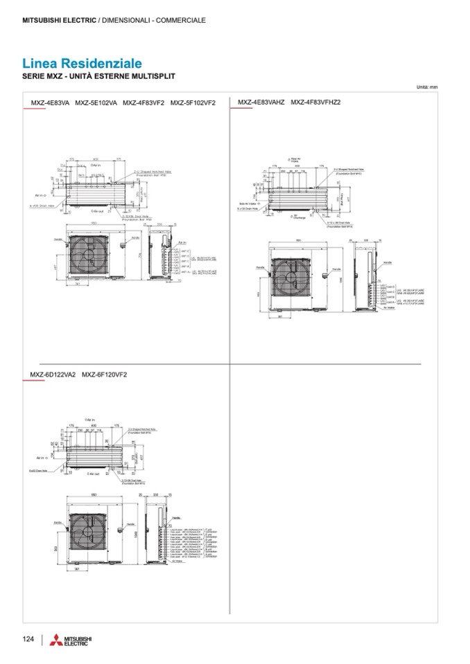
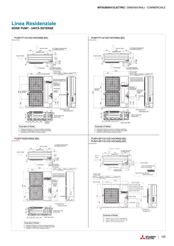
Unit : mm
LIQ
A
RGEAS
A
RE
LALIRQE
A
LRAGERAES
A
RE
LARE
LARE
6.35(1/4")FLARE
9.52(3/8")FLARE
6.35(1/4")FLARE
12.7(1/2")FLARE
2 • • •
Re2fr
•
ig
•
e
•
RreafnrtigLeIrQaUntIDLIpQipUeIDcopnipnectoionne(FcLtiAonRE(F)LøA9R.5E2) (ø39/.85F2) (3/8F)
*1
• • •
In*d1ic
•
a
• •
tIinodnicoaftSioTnOoPf SVTAOLVPEVcAoLnVnEectoionnelocctiaotniolno.cation.
MITSUBISHI ELECTRIC / DIMENSIONALI - COMMERCIALE
SERIES
UnitU:nmitm:mm
Unit : mm
Unit : mm
PUPMUYM-PY1-1P21/12/51/2154/01V4K0MVK6M(-B6(S-)BS)
PUMY-P112/125/140VKM6(-BS)
PUPMUYM-PY1-1P21/12/51/2154/01Y4K0MYK5M(-B5(S-)BS)
PSUE RMI EYS-P112 / 125 / 140VKM6(-BS)
OUOTDUDUOTOTDOOROURNUIUITNIT
PUMY-P112/125/140YKM5(-BS)
PUMY-PO1U12T/D1O25O/R14U0NVKITM6(-BS)
PUMY-PO1U12T/D1O25O/R14U0NYIKITM5(-BS)
OU
OUOTUDUTOTDOROURRNUUINTNITIT
Side
Rear Air Intake
2-U Shaped notched holes
(Foundation Bolt M10)
PUMY-SP112/125/140YKM2(-BS)
PUMY-P112 / 125 / 140YKM 5(-BS)
OUOTDUDUOTOTDOOROURNUIUITNIT
OUTDOOR UNIT
225 225
Rear ARireIanrtaAkier Intake 2-U Sh2a-pUeSdhnaoptecdhendothcohlesd holes
(Found(FaotioundBaotilot nMB1o0)lt M10)
Side ASiridInetaAkier Intake
Side Air Intake
Side Air Intake
600
Installation Feet
Air DisAchiraDrgisecharge
225
(Fou
ation Bolt M10)
45
116600 160Drain hDorlaein hole
362
1050 (Foundation Bolt M10)
362 GroundGfororuthnedpforwtherespuopwpelyr supply
225
600 600
2R2e5ar A2i2r 5Intake
2-U Shaped notched holes
InstallaInt2iso2tn5alFlaeteiotn Feet 600
225
(Foundation Bolt M10)
45
110 160
160
160
Bottom piping hole
(Knock-Out)
Drain hole
(5-ø33)
14150 1610
45 110 160 160
160
(5-Dø3ra3i(n)5-høo3le3)
116600
Example of Notes
(5-ø33)
RearAirInInstaklleationFeet2-UShapednotchedholes
362
Ground for the power supply
Terminal connection
t
a
e
nt
s
GAS pipe connection (FLARE) ø15.88 (5/8F)
2 • • •
Refrigera
s
nt LIQUID pipe connection (FLARE) ø9.52 (3/8F)
• • •
Re1fr
•
ig
•
e
•
RreafnrtigGeAraS*n1tp
•
Gi
•
p
•
AIenSdciopcaniptnieoenctoionf nSeT(FcOLtPiAonVRAE(FL)VLøEA1R5cEo.8n)8nøe(15c5/t.8i8oFn8) l(o5c/8aFtio) n.
1 • • •
Refrigerant GAS pipe connection (FLARE) ø15.88 (5/8F)
1
2
*1
• • •
In2*d1i
•
c
•
a
•
R
•
tIeinofdrniigcoeafrtaSionTntOLoIPQf SVUTAIDOLVPpEipVceAocLnVonEencetociontinonneloc(FctiLaoAtnioRlnoE.c) aøt9io.5n2. (3/8F)
• • •
Re2fr
•
ig
•
e
•
RreafnrtigLeIrQaUntIDLIpQipUeIDcopnipnectoionne(FcLtiAonRE(F)LøA9R.5E2) (ø39/.85F2) (3/8F)
*1
• • •
Indication of STOP VALVE connection location.
PUMY-P200YKM3(-BS)
70
42
42
56 42
70 60
60
70
39
60
2-12×326-1O2v×a3l6hOolveasl holes
Air Di(sFcohuanrgd(eFa4oti2oundBaotilot n2M-B5132o0×)lt3M6 1O0v)al holes
70
T6er0minalTceormnnineaclticoonnnection
From leftFtromriglheftt toTerirgmhitnal connection
105A0ir D1i0s5c0harge
2-12×36 Oval holes
From left to right
81
81
81
Air Intake
1
2
Front piping cover
8F1ront pFirpoingt pciopvinegr covRerear piping cover
56
56
39
39
0
0
53
53
0
53
0
(Foundation Bolt M10)
From left to right
Ground fGorotuhnedtrfaonrstmheGisrtsoriaounsdlminfoiesrstihoentlriannesmission line
Ground fGorocuondcefonrtrcaotGinorcnoeucnotdrnatftoriorlncocnocnetnrotrlation control
afonsrmGisrsoiounldinefor
cnhtrabtihoenxcborantnroclhbox
upplpyower supply
x
paneSlervice panel
for Handle for
56
39
moving
Air IntaAkier Intake
Air Intake
Rear pRipeinagr pciopvinegr cover
Front piping cover
Rear piping cover
BottomBoptitpoinmgphioplieng hole
(Knock(K-Onuotc)k-Out)
Bottom piping hole
(Knock-Out)
nd
4
1
7
3
6
9
6
3
2
362
1050
Ground for the
power supply
HandleHfaonrdle for Handle for
movingmoving
moving
Handle for
moving
GGrorouundGforrortuhnedtr
thGeroburnadnthfcoehr cboronacxne
power spuopwpelyr s
Ground for
the branch bo
S
p
e
o
rv
w
ic
e
e
r
S
s
p
u
ea
p
rnv
p
eic
ly
le
Handle Hfoarndle
moSveirnvgicmeopvainegl
Handle for
moving
1
1
2
2
1
2
2
6
3
6
9
*
1
4
2
6
*
1
4
2
6
*
1
4
8
5
*
1
4
8
5
*
1
4
2
6
9
7
4
1
3
3
8
1
3
3
8
6
3
2
6
3
2
1
3
3
8
6
3
2
2
6
3
6
9
3
6
9
2
6
1
3
6
1
5
4
1
3
6
1
5
4
1
3
6
1
5
4
2
6
1
3
6
1
5
4
8
6
8
6
8
6
4
0
3
3
0
4
0
4
0
3
3
0
3
3
0
*
1
4
8
5
9
7
4
8
6
*
1
4
2
6
9
7
4
*
1
4
8
5
9
7
4
1
3
3
8
2
8
4
0
3
3
0
2
8
3
7
0
3
7
0
1
9
2
8
3
7
0
4
1
7
4
1
7
2
8
3
7
0
4
1
7
1
9
1
9
1
9
ExamExpalemopfle
Example of Note
N
1
o
••
R
ft
e
N
fri
s
g
o
er
•
TDOOR UNIT
Side ASiridInetaAkier Intake225
Side Air Intake
Side Air Intake
362
ox
mov
eSpeaSrnevericvleicepapnaenlel
Hand
Handle
moving
eHfoarndlefor
moving
Exa
onnection (FLARE) ø15.88 (5/8F)
2 • • •
Refrigerant LIQUID pipe connection (FLARE) ø9.52 (3/8F)
Exam
45
225
225
600 600 Rear Air2I2nt5ake225
2-U Shaped notched holes
(Foundation Bolt M10)
d holes
0)
45
110 160
160
160
Installation Feet
362
362
1050
Rear ARireIanrtaAkier Intake
2-U Sh2a-pUeSdhnaoptecdhendothcohlesd holes
(Found(FaotioundBaotilot nMB1o0)lt M10)
InstallaIntisotnalFlaeteiotn Feet
225
600
Installation Feet
225
2-U Shaped no
(Foundation Bo
42
70 60
70
Rear Air Intake
600
225
Air DisAchiraDrgisecharge
1050 1050
Air Discharge
1050
TerminalTceormnnineaclticoonnnection
2-12×36 Oval holes
Terminal connection
Drain hole (5-ø33)
110 160
160
160
Drain hDorlaein(5h-oøl3e3()5-ø33)
Example of Notes
Drain hole (5-ø33)
45
14150 1610 116600 116600 160
1 • • •
Re1fr
•
ig
•
e
•
Rr*ea1fnr
•
ti
•
gG
•
IenArdaSinctaptGiipoAenScoofpSnipnTeOcPtoioVnAnLe(VFcELtiAocnRonE(Fn)LeøAc1tR5ioE.n8)8løo(1c55a/t.8i8oF8n) .(5/8F)
• • •
Refrigerant GAS pipe connection (FLARE) ø15.88 (5/8F)
1
2
*1
• • •
Indication of STOP VALVE connection location.
2 • • •
Re2fr
•
ig
•
e
•
RreafnrtigLeIrQaUntIDLIpQipUeIDcopnipnectoionne(FcLtiAonRE(F)LøA9R.5E2) (ø39/.85F2) (3/8F)
• • •
R
• •
e
•
frige
•
ra
• •
nt LIQUID pipe connection (FLARE) ø9.52 (3/8F)
*1
In*d1icatIinodnicoaftSioTnOoPf SVTAOLVPEVcAoLnVnEectoionnelocctiaotniolno.cation.
70
56
603942
060
53
2-12×326-1O25v×3a3l6hOolveasl holes
Air Discharge42(Found(Faotio2u-n1dB2a×ot3ilot6nMOB1vo0a)lthMol1e0s)
70
60
81
81
81
(
)
42
0 39
530
(Foundation Bolt M10)
FromleftFtromriglheftttoright
(Foundation Bolt M10)From left to right
Terminal connection
ht
ndGforor
G
ut
r
hn
o
ed
un
pf
d
orw
fo
the
r
re
th
sp
e
uopwp
o
e
w
lyr
e
s
r
u
s
p
u
pl
p
y
ly
nd fGorotGuhrneodutrnfaodnrsftomhreitshtseriaotnrnasnlminsimessisiosnionlinliene
nd fGorocGuornonducnefodnrtfrcoaortincoocnnecneotrnatriaotlniocnocnotnrotrlol
he power supply
e transmission line
ncentration control
56
3956
Front piping cover
Front pFirpoingt pciopRvieneagr cpoipvienrg cover
Front piping cRoveearr pRipeinagr pciopvinegr cover
RBeoatrtopmipipnigpicnogvheorle
(Knock-Out)
Bottom piping hole
(Knock-Out)
81
BottomBoptitpoinmgphioplieng hole
(Knock(K-Onuotc)k-Out)
Handle for
gmoving
2
1
Air Intake
IntaAkier Intake
2
1
tche
lt M1
56
39
0
53
3
7
0
1
9
4
1
7
362
leHfaonrdleHafonrdle
ingmovingmoving
for
3
6
9
3
6
9
1
3
3
8
6
3
2
6
3
2
3
6
9
6
3
2
From left to rig
Grou
Grou
Ground for t
Ground for th
Grou
Ground for co
Grou
the br
2
6
*
1
4
2
6
*
1
4
8
5
*
1
4
2
6
*
1
4
2
6
*
1
4
8
5
9
0
9
*
1
4
2
6
*
1
4
8
5
9
0
9
*
1
4
8
5
9
0
9
6
3
2
for
powe
ound for
branch box
wer supply
Handle for
moving
Air
Air Intake
2
1
1
2
ndGfororGurnodunfdorfor
anthcehthberoabxnrcahncbhobx
rspuopwpoelywrseurpsupplyply
Service panel
Servic
Handl
movin
Gr
the
po
3
6
9
1
3
6
1
5
4
2
6
1
3
6
1
5
4
4
0
3
3
0
1
3
6
1
5
4
2
6
1
3
6
1
5
4
8
6
8
6
2
8
8
6
8
6
2
6
4
0
3
3
0
4
0
3
3
0
4
0
3
3
0
3
7
0
1
9
2
8
4
1
7
3
7
0
1
9
2
8
2
8
3
7
0
1
9
4
1
7
1
3
3
8
1
3
3
8
1
3
3
8
9
0
9
4
1
7
mExpalemo
p
Re
fl
f
e
r
N
ige
o
ra
ft
n
e
t
N
G
s
A
o
S
te
pip
s
e c
1
•• •
ple of Notes
DUOOTODORORUONURINTUITNIT
Example of Notes
Example of Notes
ExamExpalemopfleNofteNsotes
PUMY-SP112/125/140VKM2 -BS
PUPMUYM-PY2-0P02Y0K0MYK3M(-B3(S-)BS)
PUPMUYM-SYP-1S1P21/12/51/2154/01V4K0MVK2M(-B2(S-)BS)
PUPMUYM-PY2-P0O20U0Y0TKYDMKO3MO(-3RB(-SUB)NS)IT
PUMYP-SUPM1Y12-S/1P2151/21/4102V5K/1M420(V-BKSM)2(-BS)
PUMY-SP112/125/140YKM2(-BS)
PUPMUYM-OSYUP-T1SD1P2O1/O12R/51U/21N54I/T01Y4K0MY(K2M(-B)2(S-)BS)
PUMY-SP112/125/140YKM2 -BS
OOUUTOTD
ion
Side A2i2r 5Int2a2k25e25
ASirididIenetAaAikrierInIntatakkee
362
600600600
InstaInllsaItntaisolltanatilFolaenteioFteneFteet
222525 225
1
• • •
Re1fr
•
ig
•
e
•
RreafnrtigGeAraSntpGipAeScopnipnectoionne(FcLtiAonRE(F)LøA1R9E.0)5ø(139/.40F5) (3/4F)
45
110 160
160
Drain hole (5-ø33)
45 110 160
Example of Notes
225
600
ReaRreAaRireAIanirItnaIAsnktiteralIklnaetaiokneFeet
(F(oFuonudn(FadotaiotuionndBaBotoilotltnMB11o0)l)t M10)
Air Discharge
60
60
From left to right
1050 2-12×36 Oval holes
For the
Air DisAchiraDrgisecharge
362
2-(1F2o×u3n26d-1aO2tivo×an3l6BhoOoltveaMsl1h0o)les
power supply
(Found(FaotioundBaotilot nMB1o0)lt M10)
For the
branch box
power supply
For the
transmission line
For concentrat
control
1050
1050 1050
Termina
F
l
ro
c
m
Toenr
l
nm
e
e
ft
icn
t
ta
o
iol
r
cn
ig
o
h
n
t
nection
FromFolretfhtetFororimghlteftFtorrtihgeht
For the
For concentration
control
For concenFtorar tcioncentration
160 160
160 Drain hDorlaein(5h-oøl3e3()5-ø33)
GAS pipe connection (FLARE) ø19.05 (3/4F)
LIQUID pipe connection (FLARE) ø9.52 (3/8F)
*1
• • •
Indication of STOP VALVE connection location.
1 • • •
Refrigerant GAS pipe connection (FLARE) ø19.05 (3/4F)
ExamExpalemopfleNofteNsotes
*1
• • •
Indication of STOP VALVE connection location.
2 • • •
Refrigerant LIQUID pipe connection (FLARE) ø9.52 (3/8F)
81
81
160
Front piping cover
Rear piping cover
2-2U-USSh2ah-paUpeSeddhnanopotectcdhhenedothcohllesds holes
225
56
39
0
53
56 42
5639 56
390 6039
053 0
42
42
60
Terminal connection
AirDischarge
25-312×3653Ovalholes
42
(Foundation Bolt M10)
Terminal connection
81
Rear pRipeinagr pciopvinegr cover
Bottom piping hole
(Knock-Out)
transmission line
For the For theFoprotwher suFpoprlytheFor the For the
power supply
branch box
power suppolywer bsruapnpclhy
G
bo
ro
xbr
u
a
n
c
d
ht
f
rba
o
n
r
xs
t
m
h
is
e
si
p
otrn
o
anl
w
isnmei
r
ssico
u
on
p
nl
p
tinro
l
e
y
l
power suppolywer supply
Ground for the transmission line
control
Ground for the power supply
GroGuronudnGdforforrutthnhede ptfroaornwstmhereisspuiopnwplielnyresupply
GroundforconcenGtrarotiuondcofonrtrol
rfaonrstmtheiestsbriaroansclmihniesbsoioxn line
cefonrtrcpaotoinowcnercnsotrunaptrpiolyln control
Service panel
or
h box
pply
anel
e for
g
81
Rear piping cover
Ground for concentration control
Handle for
moving
Air Intake
Air IntaAkier Intake
Front piping cover
Front pFirpoingt pcBiopovintetgor mcopviepring hole
(Knock-Out)
BottomBoptitpoinmgphioplieng hole
(Knock(K-Onuotc)k-Out)
Drain hole (5-ø33)
Air Intake
4
1
7
362 362
GroundfGorotuhnedt
GroundfGorocuond
Ground for
the branch box
GropuonwderfGosruopupnlyd f
thebrantcheborxanc
powServsicupepopwalyenrelsu
Handle for
ServicmeopSvaeinrgveilce p
Handle fHorandl
moving movin
1
3
3
8
3
6
9
6
3
2
2
6
3
9
3
4
5
0
3
9
3
3
9
3
4
5
0
9
8
6
9
8
6
2
6
1
3
6
1
5
4
1
3
6
1
5
4
1
3
6
1
5
4
2
6
2
6
3
6
9
3
6
9
3
6
9
1
3
3
8
1
3
3
8
6
3
2
1
3
3
8
6
3
2
6
3
2
4
0
3
3
0
4
0
4
0
3
3
0
3
3
0
4
0
3
3
0
2
8
2
8
3
7
0
1
9
4
1
7
3
7
0
1
9
2
8
3
7
0
1
9
4
1
7
2
8
3
7
0
1
9
4
1
7
1
3
6
1
5
4
8
6
8
6
8
6
8
6
9
8
6
3
9
3
4
5
0
4
5
0
9
8
6
45 14150 1610
1 •
1
• •
16600 160
Example
Refrigerant
2
• ••
R
N
ef
o
rig
t
era
s
nt
o f
125
F
F
F
F

