Esempi di installazione
Installation examples
A
Esempi di staffaggio relativi a tubazioni che trasportano
acqua calda:
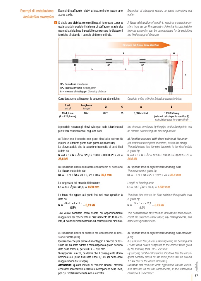
1 Si abbia una distribuzione rettilinea di lunghezza L, per la
quale andrà impostato il sistema di staffaggio; grazie alla
geometria della linea è possibile compensare le dilatazioni
termiche sfruttando il cambio di direzione finale.
Examples of clamping related to pipes conveying hot
water:
A linear distribution of length L, requires a clamping sy-
stem to be set up. The geometry of the line is such that the
thermal expansion can be compensated for by exploiting
the final change of direction.
Direzione del flusso Flow direction
L
DL
FP
SP
SP
i
s
i
s
FP= Punto fisso Fixed point
SP= Punto scorrevole Sliding point
i
s
= Interassi di staffaggio Clamping distance
FP
FP
LB
Considerando una linea con le seguenti caratteristiche:
63x4,5 mm
20 m
70°C
(A = 826,6 mmq)
Consider a line with the following characteristics:
Ø est.
Lunghezza
ext. Ø
Lenght
Dt
C
a
E
33
0,026 mm/mK
19000 N/mmq
(valore di calcolo per lo specifico Ø)
(calculation value for a specific Ø)
the stresses developed by the pipe on the fixed points can
be derived considering the following cases:
a) Pipeline secured with fixed points at the ends
(an additional fixed point, therefore, before the fitting).
The axial stress that the pipe transmits to the fixed points
is given by:
N=A•E•a•Dt=826.6•19000•0.000026•70=
28.6 kN
b) Pipeline free to expand with bending arm
The expansion is given by:
DL = L • a • Dt = 20 • 0.026 • 70 = 36.4 mm
Length of bending arm:
LB = 33 • √(63 • 36.4) = 1.580 mm
The force that acts on the fixed points in the specific case
is given by:
è possibile ricavare gli sforzi sviluppati dalla tubazione sui
punti fissi considerando i seguenti casi:
a) Tubazione bloccata con punti fissi alle estremità
(quindi un ulteriore punto fisso prima del raccordo).
Lo sforzo assiale che la tubazione trasmette ai punti fissi
è dato da:
N=A•E•a•Dt=826,6•19000•0,000026•70=
28,6 kN
b) Tubazione libera di dilatare con braccio di flessione
La dilatazione è data da:
DL = L • a • Dt = 20 • 0,026 • 70 = 36,4 mm
La lunghezza del braccio di flessione:
LB = 33 • √(63 • 36,4) = 1580 mm
La forza che agisce sui punti fissi nel caso specifico è
data da:
(3 • E • J • DL)
N ~-- ---------------------------- = 0,19 kN
Tale valore nominale dovrà essere poi opportunamente
maggiorato per tener conto di disassamento struttura-col-
lare, di eventuali disallineamenti e di carichi statici e dinamici.
c) Tubazione libera di dilatare ma con braccio di fles-
sione ridotto (LBr)
Ipotizzando che per errore di montaggio il braccio di fles-
sione LB sia stato ridotto a metà rispetto a quello corretto
dato dalla formula, per cui LBr = 790 mm.
Sviluppando i calcoli, ne deriva che il conseguente sforzo
nominale sui punti fissi sarà circa 1,5 kN (al netto delle
maggiorazioni di cui sopra).
Attenzione: questa ipotesi di “braccio ridotto” provoca
eccessive sollecitazioni e stress sui componenti della linea,
per cui l’installazione fatta non è corretta.
(3 • E • J • DL)
(LB
3
)
N ~-- -------------------------------- = 0.19 kN
(LB
3
)
This nominal value must then be increased to take into ac-
count the structure-collar offset, any misalignments, and
static and dynamic loads.
b) Pipeline free to expand with bending arm reduced
(LBr)
It is assumed that, due to assembly error, the bending arm
LB has been halved compared to the correct value given
by the formula, thus LBr = 790 mm.
By carrying out the calculations, it follows that the conse-
quent nominal stress on the fixed points will be around
1.5 kN (net of the above increases).
Caution: this “reduced arm” hypothesis causes exces-
sive stresses on the line components, so the installation
carried out is incorrect.
57

