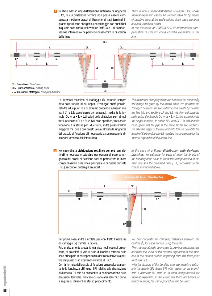
2 Si abbia adesso una distribuzione rettilinea di lunghezza
L tot, la cui dilatazione termica non possa essere com-
pensata mediante bracci di flessione ai tratti terminali in
quanto questi sono obbligati a uno staffaggio con punti fissi.
In questo caso andrà realizzato un OMEGA o U di compen-
sazione intermedio che permette di assorbire le dilatazioni
della linea.
There is now a linear distribution of length L tot, whose
thermal expansion cannot be compensated for by means
of bending arms at the end sections since these are to be
secured with fixed points.
In this scenario, an OMEGA or U of intermediate com-
pensation is created which absorbs expansion of the
line.
L1
FP
SP
SP
i
s
i
s
FP= Punto fisso Fixed point
SP= Punto scorrevole Sliding point
i
s
= Interassi di staffaggio Clamping distance
DL1
Ltot
FP
LM
DL2
L2
SP
SP
FP
i
s
i
s
LB
LB
Le interassi massime di staffaggio (is) saranno sempre
date dalla tabella di cui sopra. L'“omega” andrà posizio-
nato fra i due punti fissi di estremo dividendo la linea in due
tratti L1 e L2; calcoleremo per entrambi, mediante la for-
mula DL = a • L • Dt i valori delle dilatazioni per i singoli
tratti, ottenendo DL1 e DL2. Nel caso specifico, visto che la
tubazione è la stessa per i due tratti, andrà preso il valore
maggiore fra i due e con questo verrà calcolata la lunghezza
del braccio di flessione LB necessaria a compensare le di-
latazioni termiche dell’intera linea.
3 Nel caso di una distribuzione rettilinea con più rami de-
rivati, è necessario calcolare per ognuna di esse la lun-
ghezza dei bracci di flessione così da permettere la libera
compensazione della linea principale e di quelle derivate
(TEE) secondo i criteri già enunciati.
The maximum clamping distances between the centres (is)
will always be given by the above table. We position the
“omega” between the two extreme end points by dividing
the line into two sections L1 and L2. We then calculate for
both, using the formula DL = a • L • Dt the expansion for
the single sections, to obtain DL1 and DL2. In this specific
case, given that the pipe is the same for the two sections,
we take the larger of the two and with this we calculate the
length of the bending arm LB required to compensate for the
thermal expansion of the entire line.
In the case of a linear distribution with deviating
branches, we calculate for each of them the length of
the bending arms so as to allow free compensation of the
main line and the branched ones (TEE), according to the
criteria mentioned above.
L1
Direzione del flusso Flow direction
DL1
D
FP
SP
SP
FP
D1
FP
LB1
Per prima cosa andrà calcolata per ogni tratto l’interasse
di staffaggio (is) tramite la tabella.
Poi, analogamente a quanto già visto negli esempi prece-
denti, si calcolerà il valore della dilatazione termica della
linea principale in corrispondenza del tratto derivato a par-
tire dal punto fisso ricavando il valore di DL1.
Con la formula del braccio di flessione verrà calcolata per-
tanto la lunghezza LB1 (pag. 57) relativa alla diramazione
di diametro D1 tale da consentire la compensazione delle
dilatazioni termiche. Nel caso ci siano altri stacchi o curve
a seguire si utilizzerà lo stesso procedimento.
We first calculate the clamping distances between the
centres (is) for each section using the table.
Then, as has already been seen in previous examples, we
calculate the value of the thermal expansion of the main
line at the branch section beginning from the fixed point
to obtain DL1.
With the formula of the bending arm, we therefore calcu-
late the length LB1 (page 57) with respect to the branch
with a diameter D1 such as to allow compensation for
thermal expansion. In the event that there are breaks or
bends to follow, the same procedure will be used.
58

