RENOVA ULTRA panel
Code
10 16 64
10 16 65
10 16 66
Specifications
Material Comp.
strength
10% kPa
EPS400 400
EPS300 300
EPS300 300
Therm. Res.
A
m
2
K/W
mm
0.27
1400
0.75
1400
1.25
1400
B
H
Sur.
mm
mm
m
2
800
20
1.12
800
35
1.12
800
50
1.12
Dimensional drawing
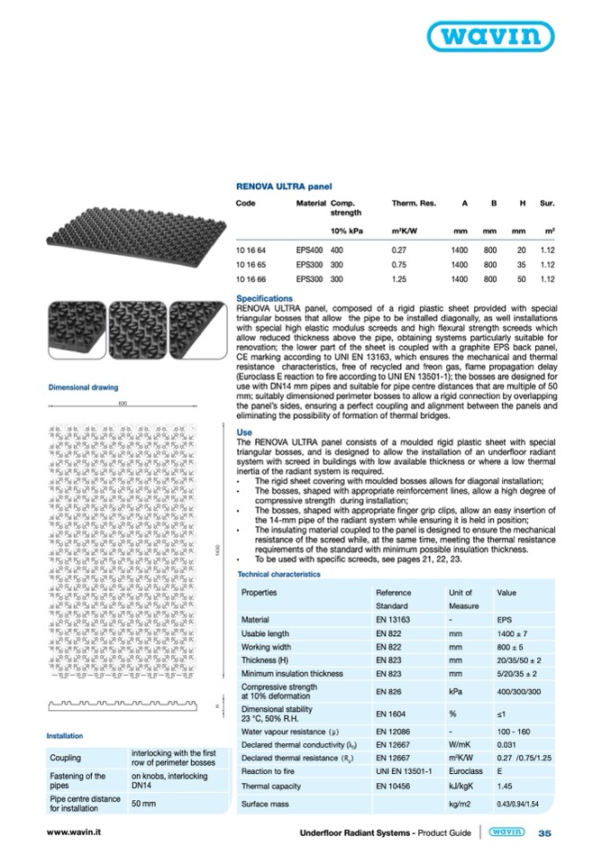
RENOVA ULTRA panel, composed of a rigid plastic sheet provided with special
triangular bosses that allow the pipe to be installed diagonally, as well installations
with special high elastic modulus screeds and high flexural strength screeds which
allow reduced thickness above the pipe, obtaining systems particularly suitable for
renovation; the lower part of the sheet is coupled with a graphite EPS back panel,
CE marking according to UNI EN 13163, which ensures the mechanical and thermal
resistance characteristics, free of recycled and freon gas, flame propagation delay
(Euroclass E reaction to fire according to UNI EN 13501-1); the bosses are designed for
use with DN14 mm pipes and suitable for pipe centre distances that are multiple of 50
mm; suitably dimensioned perimeter bosses to allow a rigid connection by overlapping
the panel’s sides, ensuring a perfect coupling and alignment between the panels and
eliminating the possibility of formation of thermal bridges.
Use
The RENOVA ULTRA panel consists of a moulded rigid plastic sheet with special
triangular bosses, and is designed to allow the installation of an under
floor radiant
system with screed in buildings with low available thickness or where a low thermal
inertia of the radiant system is required.
•
The rigid sheet covering with moulded bosses allows for diagonal installation;
•
The bosses, shaped with appropriate reinforcement lines, allow a high degree of
compressive strength during installation;
•
The bosses, shaped with appropriate finger grip clips, allow an easy insertion of
the 14-mm pipe of the radiant system while ensuring it is held in position;
•
The insulating material coupled to the panel is designed to ensure the mechanical
resistance of the screed while, at the same time, meeting the thermal resistance
requirements of the standard with minimum possible insulation thickness.
•
To be used with specific screeds, see pages 21, 22, 23.
Installation
Coupling
Fastening of the
pipes
Pipe centre distance
for installation
interlocking with the first
row of perimeter bosses
on knobs, interlocking
DN14
50 mm
Technical characteristics
Properties
Material
Usable length
Working width
Thickness (H)
Minimum insulation thickness
Compressive strength
at 10% deformation
Dimensional stability
23 °C, 50% R.H.
Water vapour resistance (μ)
Declared thermal conductivity (λ
D
)
Declared thermal resistance (R )
D
Reaction to fire
Thermal capacity
Surface mass
Reference
Standard
EN 13163
EN 822
EN 822
EN 823
EN 823
EN 826
EN 1604
EN 12086
EN 12667
EN 12667
UNI EN 13501-1
EN 10456
Unit of
Value
Measure
-
EPS
mm
1400 ± 7
mm
800 ± 5
mm
20/35/50 ± 2
mm
5/20/35 ± 2
kPa
400/300/300
%
≤1
-
100 - 160
W/mK
0.031
m
2
K/W
0.27 /0.75/1.25
Euroclass
E
kJ/kgK
1.45
kg/m2
0.43/0.94/1.54
www.wavin.it
Underfloor Radiant Systems - Product Guide
35

