74
75
CRI AT 903
CRI AT 904
Pressione | Druck | Pression
Pressure | Pressión | Давление
2 bar
3 bar
4-6 bar
Tubazione | Röhre | Tubulure
Pipe fittings | Tuberia | Труба
ø
ø
ø
N. Flussometri | nzahl der Druckspüler | Numero des pièces installées
No. of flush-valves | Núméro de fluxómetros | Количество сливных
клапанов
1
2
3
4
5-7
8-10
Flussometro | Druckspüler | Fluxmetre
Flush valve | Fluxómetros | Сливной клапан
Flussometro | Druckspüler | Fluxmetre
Flush valve | Fluxómetros | Сливной клапан
NOTE PER L’INSTALLAZIONE | INSTALLATION NOTES | ЗАМЕЧАНИЯ ПО УСТАНОВКЕ
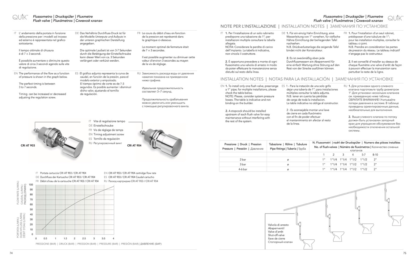
IT L’ andamento della portata in funzione
della pressione per i modelli ad incasso
ed esterno é rappresentata nel grafico
sottostante.
Il tempo ottimale di chiusura
é di 7 ± 3 secondi.
È possibile aumentare o diminuire questo
valore di circa 3 secondi agendo sulla vite
di regolazione.
EN The performance of the flow as a function
of pressure is shown in the graph below.
The perfect timing is between
3 to 7 seconds.
Timing can be increased or decreased
adjusting the regulation screw.
DE Das Verhältnis Durchfluss-Druck ist für
die Modelle Unterputz und Aufputz in
der unteren graphischen Darstellung
angegeben.
Die optimale Laufzeit ist von 3-7 Sekunden
durch die Betätigung der Einstellschraube
kann dieser Wert von ca. 3 Sekunden
verlängert oder verkürzt werden.
ES El gráfico adjunto representa la curva de
caudal, en función de la presión, para el
modelo exterior y empotrado.
El tiempo óptimo de corte es de 7-3
segundos. Es posible aumentar i disminuir
dicho valor, ajustando el tornillo
de regulación.
IT Vite di regolazione tempo
DE Einstellschraube
FR Vis de réglage de temps
EN Timing adjustment screw
ES Tornillo da regulación
RU Регулировочный винт
FR Le cours du débit d’eau en fonction
de la pression est représenté dans
le graphique ci-dessous.
Le moment optimal de fermeture était
de 7 ± 3 secondes.
Il est possible augmenter ou diminuer cette
valeur d’environ 3 secondes au mayen
de la vis de réglage.
RU Зависимость расхода воды от давления
нажатия показана на приведенном
ниже графике.
Идеальная продолжительность
составляет 3—7 секунд.
Продолжительность срабатывания
можно увеличить или уменьшить
с помощью регулировочного винта.
IT 1. Per l’installazione di un solo rubinetto
predisporre una tubazione da 1”; per
installazioni multiple consultare la tabella
allegata.
NOTA: Considerare le perdite di carico
dell’impianto. La tabella è indicativa,
non vincola il costruttore.
2. É opportuno prevedere a monte di ogni
flussometro una valvola di arresto in modo
da poter effettuare le manutenzione senza
disturbi sul resto della linea.
DE 1. Für ein einzig Hahn Einrichtung, eine
Wasserleitung von 1” vorsehen, für vielfache
Hähne Einrichtung der beiliegenden Tafel
nachsehen.
N.B. Drückverlustanlage die zeigende Tafel
bindet nicht der Konstrukteur.
2. Es ist zweckmäßig oben jede
Durchflussmessern ein Absperrventil für
eine einfach Wartung ohne Störung auf den
Rest von der Strecke ausführen können.
FR 1. Pour l’installation d’un seul robinet,
prédisposer d’une tubulure de 1”;
pour les installation multiples, consulter le
tableau ci-joint.
N.B. Prendre en considération les pertes
de pression du réseau. Le tableau indicatif
n’engage pas le costructeur.
2. Il est conseillé d’installer au-dessus de
chaque fluxmètre une valve d’arrêt de façon
à pouvoir effectuer la manutention sans
perturber le reste de la ligne.
IT Portata cartuccia CRI AT 903 / CRI AT 904
DE Durchfluss der Kartusche CRI AT 903 / CRI AT 904
FR Débit d’eau de la cartouche CRI AT 903 / CRI AT 904
EN CRI AT 903 / CRI AT 904 cartridge flow rate
ES CRI AT 903 / CRI AT 904 Caudal cartucho
RU Расход картриджа CRI AT 903 / CRI AT 904
PRESSIONE (BAR) | DRUCK (BAR) | PRESSION (BAR) | PRESSURE (BAR) | PRESIÓN (BAR) | ДАВЛЕНИЕ (БАР)
Valvola di arresto
Absperrventil
Valve d’arrêt
Shut-off valve
Ilave de cierre
Стопорный клапан
INSTALLATION NOTES | NOTAS PARA LA INSTALLACIÓN | ЗАМЕЧАНИЯ ПО УСТАНОВКЕ
EN 1. To install only one flush valve, prearrange
a 1” pipe; for multiple installations, please
check the table below.
NOTE: Please, consider system pressure
losses. The table is indicative and not
binding on the builder.
2. A stopcock should be installed
upstream of each flush valve for easy
maintenance without interfering with
the rest of the system.
ES 1 - Para la instación de una solo grifo
dejar una tuberia de 1”; para instalaciones
múltiples consultar la tabla adjunta.
N.B. tener en cuenta las pérdidas
de carga de toda la installacion.
La tabla indicativa no obliga al constructor.
2 - Es aconsejable montar una liave
de cierre en cada fluxómetro
con el fin de poder efectuar
el mantenimiento sin afectar al resto
de la linea.
RU 1. Для установки одного сливного
клапана подготовьте трубу диаметром
1”. Для установки нескольких клапанов
см. приведенную ниже таблицу.
ОБРАТИТЕ ВНИМАНИЕ! Учитывайте
потери давления в системе. В таблице
приведены ориентировочные данные,
необязательные для выполнения.
2. Выше сливного клапана по потоку
должен быть установлен запорный
кран для упрощения обслуживания без
необходимости отключения остальной
системы.
1”
1”
1”
1”1/4
1”1/4
1”1/4
1”1/4
1”1/4
1”1/4
1”1/2
1”1/2
1”1/2
1”1/2
1”1/2
1”1/2
2”
2”
2”
P
O
R
T
A
T
A
(
L
/
M
I
N
.
)
F
L
O
W
R
A
T
E
(
L
/
M
I
N
.
)
D
U
R
C
H
F
L
U
S
S
(
L
/
M
I
N
)
D
E
́
B
I
T
D
’
E
A
U
(
L
/
M
I
N
.
)
C
A
U
D
A
L
(
L
/
M
I
N
.
)
Р
А
С
Х
О
Д
(
Л
/
М
И
Н
)

